Lab 6 - Closed-loop Control(PID)
Prelab
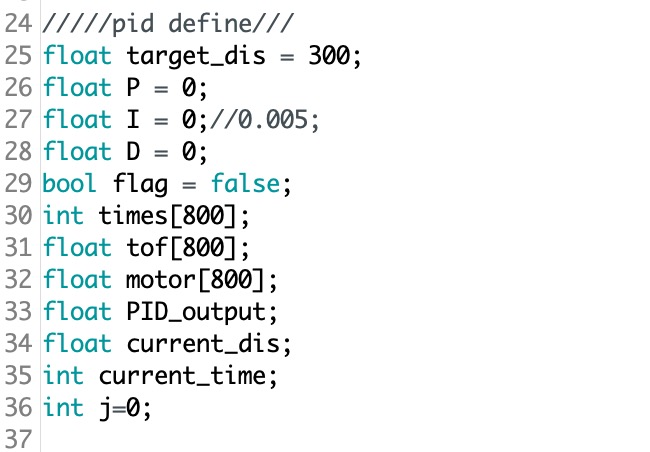
I create a new Arduino code file and combine the necessary code from lab2 and lab3 to get a good setup for the Bluetooth and the ToF sensor. This is very similar to the task we did in lab 2. I first define all the variable I need as a global variable at the very top of the Arduino code. The code screenshot is shown below.
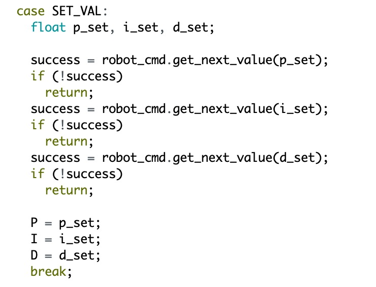
In this lab, I create three cases in the handler command section. The first one is called "SET_VAL", which is shown below. This is helpful to set the Kp, Ki, and Kd values in the Jupyter notebook. With this code, we do not need to upload the whole code to the Artemis board to test the PID value.
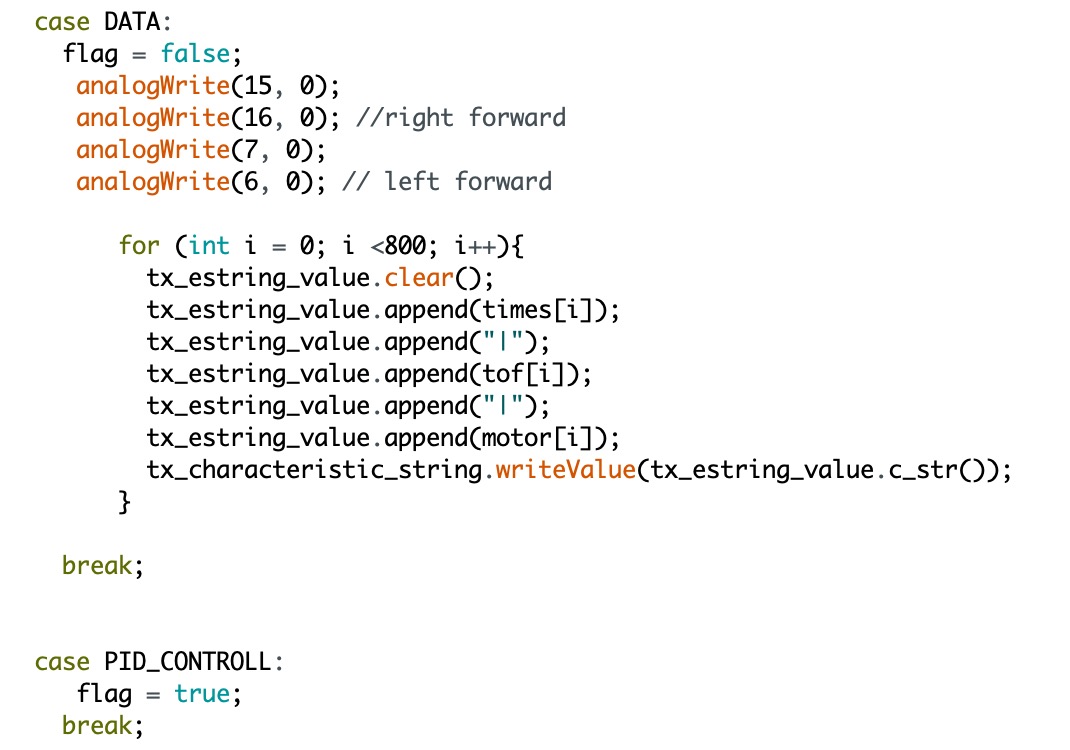
The cases shown below are used to control the car moving and also send the data to the computer. The case "PID_CONTROLL" is help to turn on the car and start to get the sensor distance and calculate the PMW value. The case "DATA" is used to receive the data array from Artemis. But before that, I set the flag to false to stop the car first.
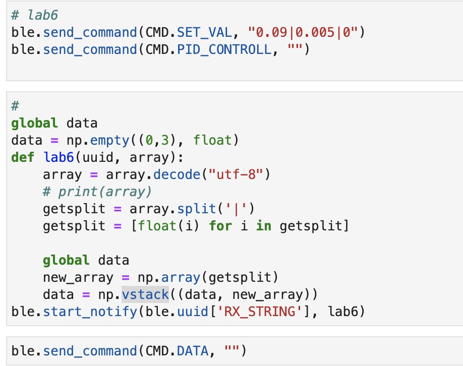
Then in python code, we still need a notification handler to help to receive the data from Artemis. But before that, we need to send the command with the command type "SET_VAL" to set the PID value and "PID_CONTROLL" to make the car start moving. And then, the command type "DATA" can be run to store all the data monitored into array and ready to get the plot.
PID Discussion
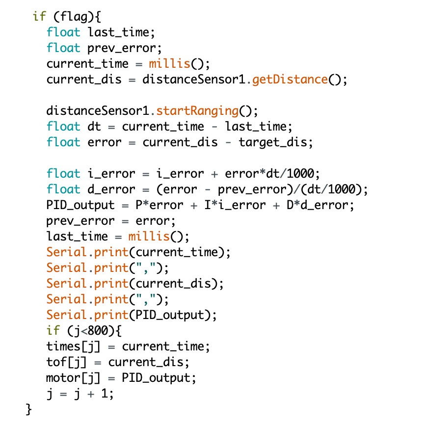
PID (proportional, integral, and derivative) control is a closed-loop control. For the P control, the output will be proportional to the increase as the error increase. P control only is useful when you want to design a controller quickly, but it is not perfect. In my Arduino code. I can get the error by using the ToF sensor to get the current distance and use that to minus the target distance, which is 300mm. Then, the output will be P*error.
For the I (integral) control, this term seeks to eliminate the residual error by adding a control effect due to the historic cumulative value of the error. It is used to sum the error over time, so a small error term can cause the response speed system to increase slowly. Therefore, the purpose of the I controller is to tune the system to get a good reaction time. In the Arduino code, I define the i_error and add every error term up during the time change, which is "i_error = i_error + error*dt/1000", where the dt is current_time - last_time.
For D (derivative) control, it calculates the rate of change of the error. As the error change becomes larger, the derivative factor will become larger. This D controller is helpful to deal with the overshoot generated by the P and I controller. In the Arduino code, I use the current error to minus the previous error and all together divided it by the dt, which is d_error = (error - prev_error)/(dt/1000).
Range/Sampling time Discussion
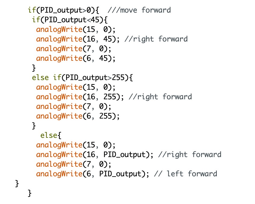
After getting the data in the Jupyter Notebook, I found the sampling time is around 10ms. So, the frequency reaches 200 Hz, which is very fast. Also, as we discussed in lab 5, there is a deadband of the motor that the value below the deadband will not be able to overcome the static friction. So, I set the deadband value to 45 in this lab and make a loop to prevent this kind of situation. The detailed code is shown in the next section.
Graphs, code, videos, images, discussion of reaching task goal
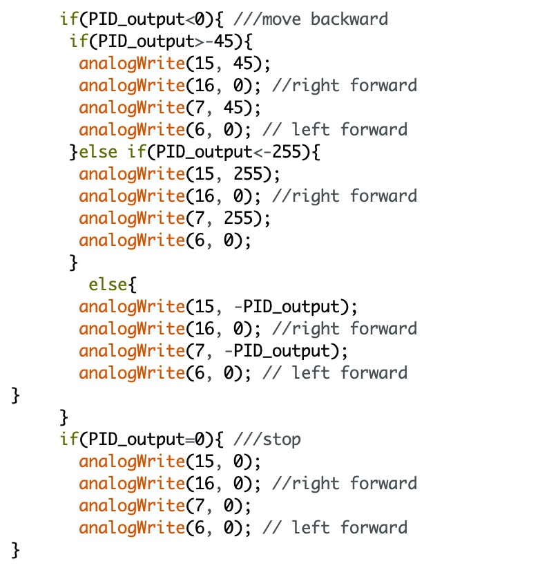
The code below is the main loop to set the PID control for the car. After calculating the PID_output value, I specify them into three big conditions to check if the sensor is close enough to the obstacle and then make the reaction of moving forward, backward, or stopping. In the moving conditions, I set two extra loops to prevent the PWM value from not greater than the max value 255 and not less than the deadband value 45.
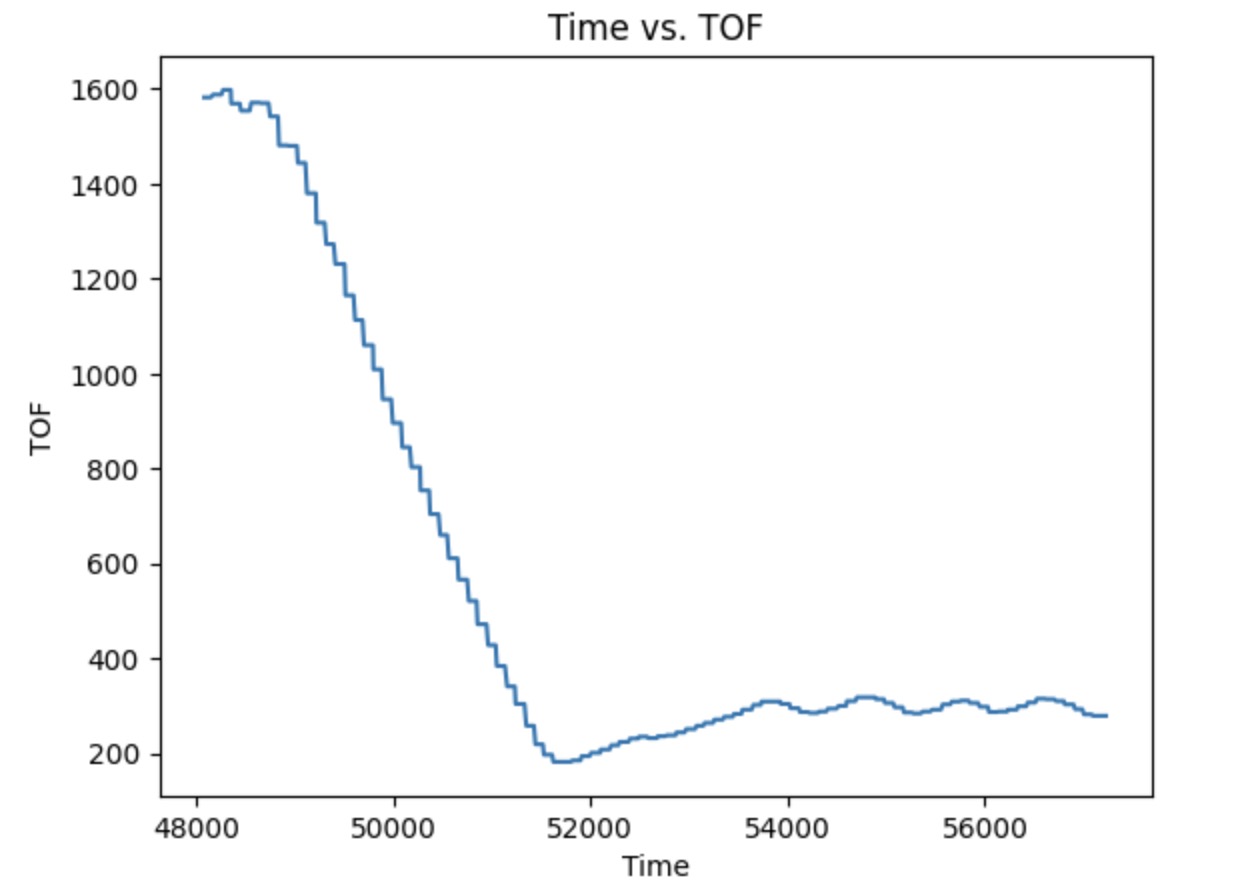
I first set I and D values to be 0 and tried to find an appropriate P value. I start from 0.001 and slowly increase that. Until getting to 0.06, the car performs well. The video below shows the car moving with P=0.06, I=0, and D=0.
These two plots shown below are the Tof vs time and Motor input vs time with P=0.06, I=0, and D=0.
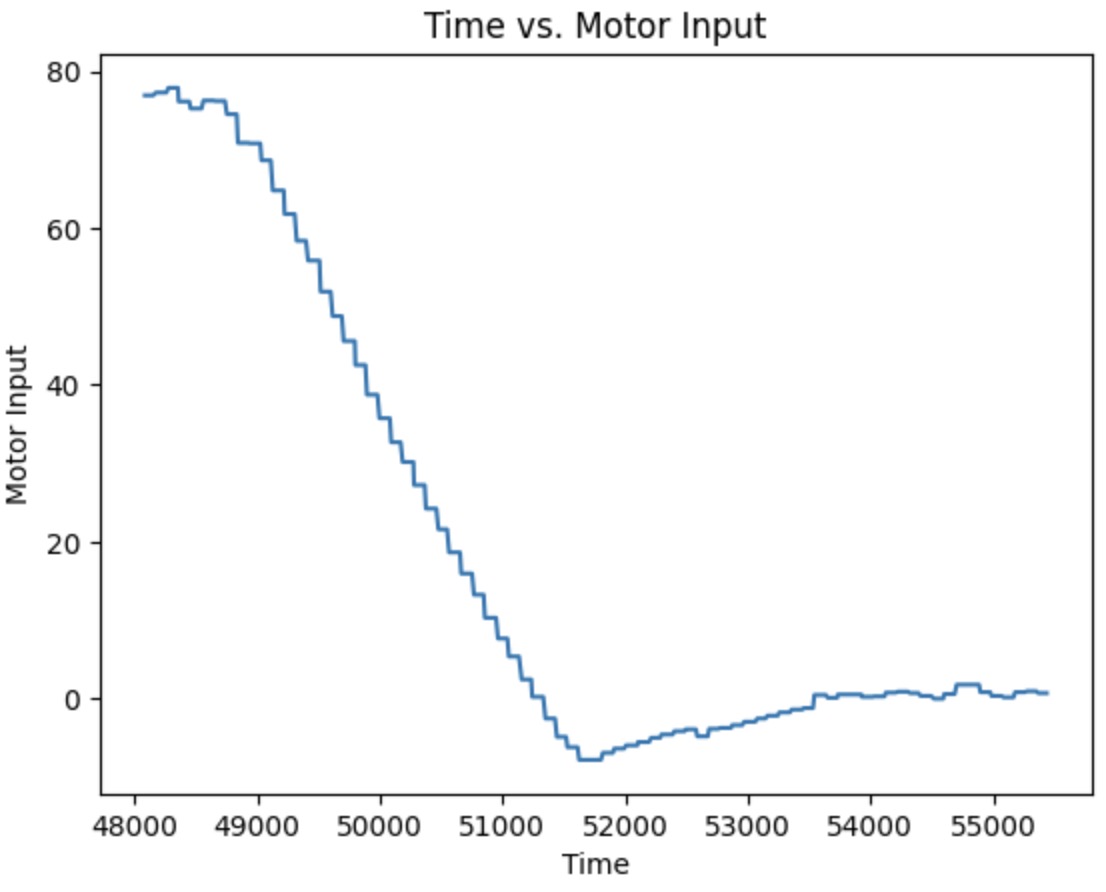
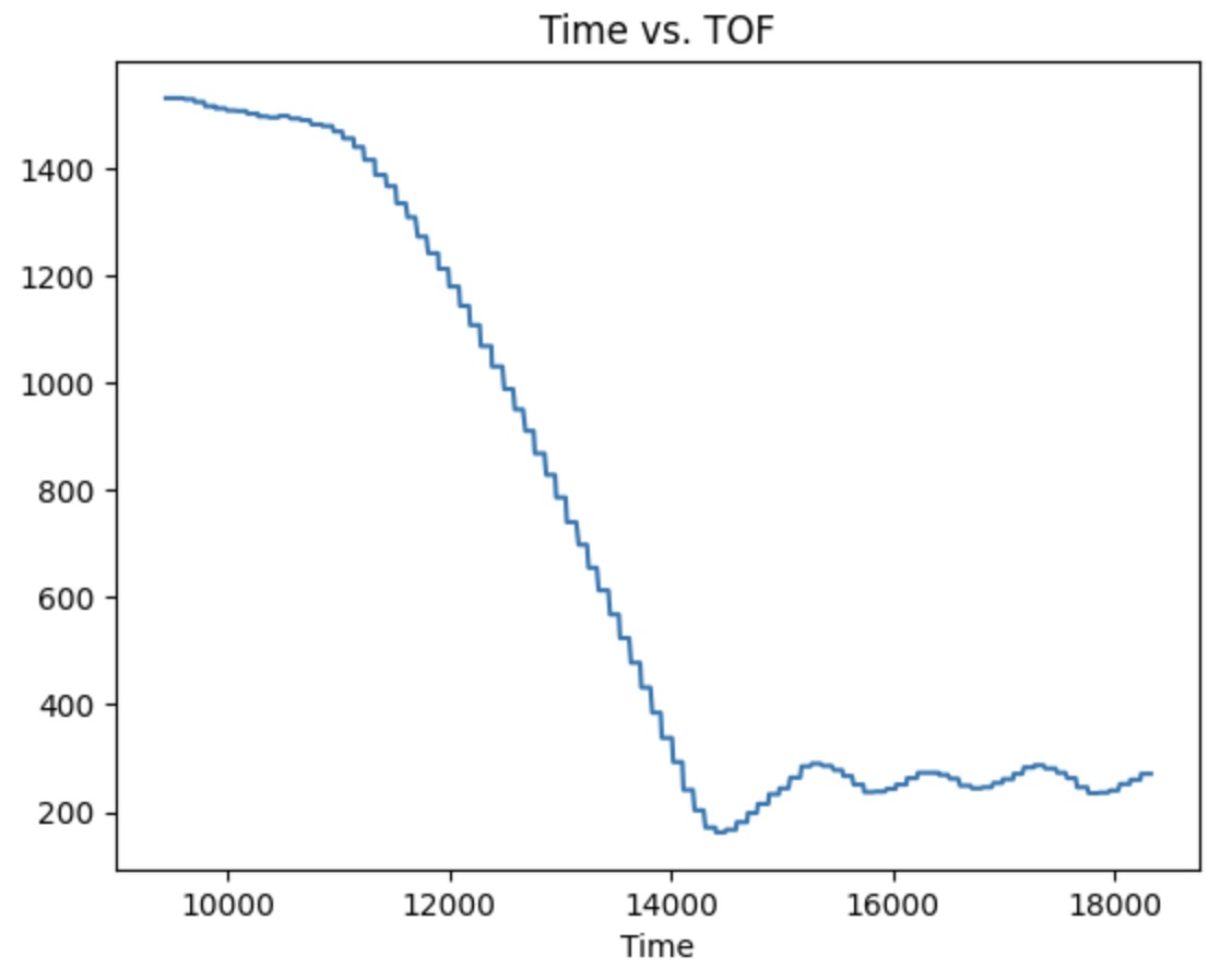
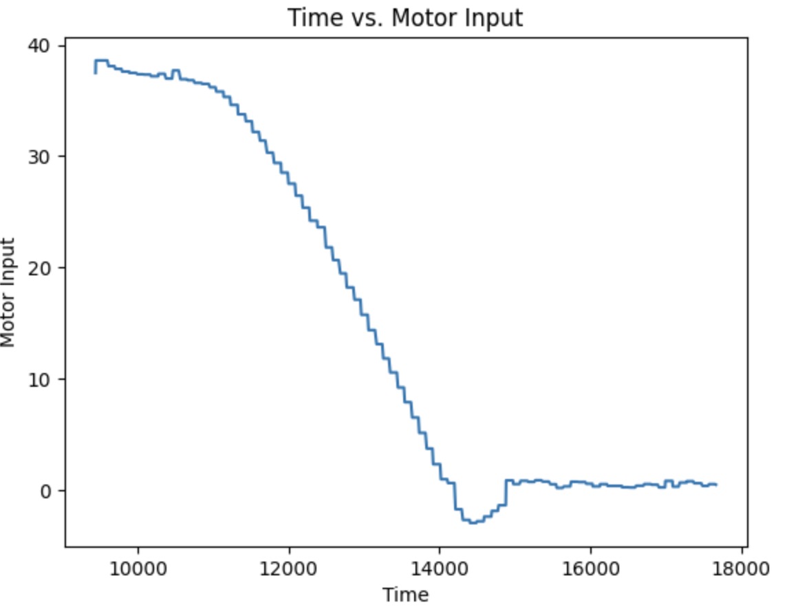
Then I have to add an I (Integral) controller. Before tunning it, I have to half the P value, which becomes 0.03. Then, I set the I value to 0.001 and found that it will hit the wall. So, the value should be even lower than 0.001. I decrease it and made several tries. When the I value equals 0.0005, the car performs the best. The video below shows the car's performance with P=0.03, I=0.0005, and D=0.
These two plots shown below are the Tof vs time and Motor input vs time with P=0.03, I=0.0005, and D=0.
(5000) Wind-up implementation and discussion
Integrator wind-up is a phenomenon that occurs in control systems that use integral feedback. When the system's output reached its maximum or minimum limit, the integral term in the feedback controller can continue to accumulate error, causing the system to overshoot its setpoint when the output becomes unsaturated. To prevent the integrator wind-up can be done by setting a maximum value for the integral term. The maximum value will depend on saturation limit of the output. The higher limit for the output for the car is 255.