Lab 12 - Path Planning and Execution
Objective
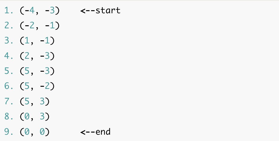
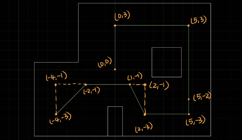
The last lab is required to make the robot passing every point shown below as quickly and accurately as possible.
The method I use is applying the PID control directly without localization, because localization requires the rotate 360 to check the localization when the robot move to the new place, which is very time-cosuming. And also, as the result shown in the lab 11, the localization is not exactly accurate. Because of the speed of two motors are not exactly same, that will cause even more error. However, the most importance factor to choose this method is that the PID implementation is easier.
Code Implementation
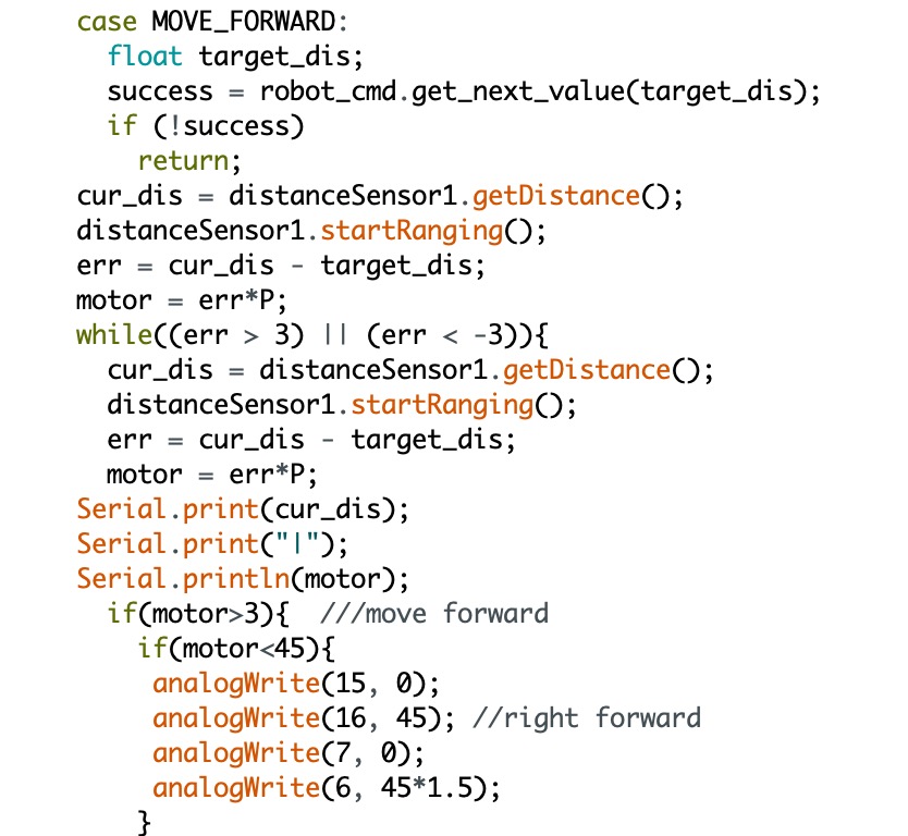
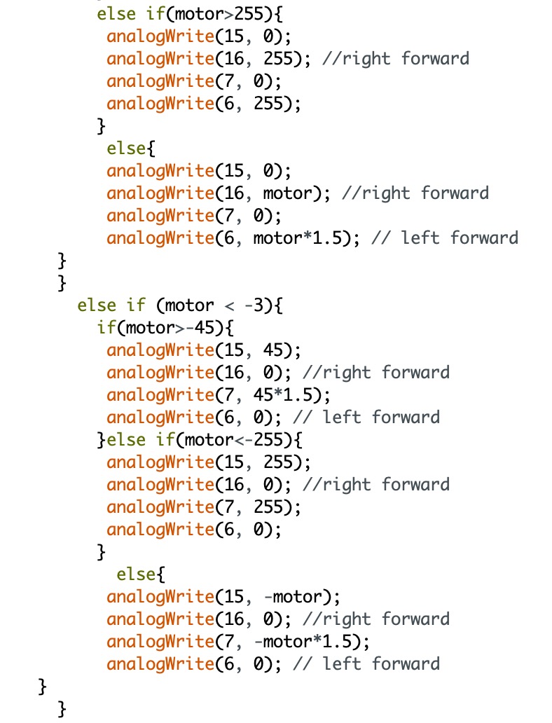
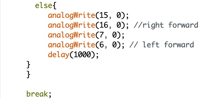
To implement the PID control, I create a while loop in the CASE session. I first calculate the error at the starting point, and then use the while loop to determine whether the error result is acceptable. If not, the code will go into the while loop to execute the PID control command again until the error is located within the acceptable range. This code is very similar with the code in lab 6 for PID control. The only difference here is that I have to create the loop manually. The code is attached below.
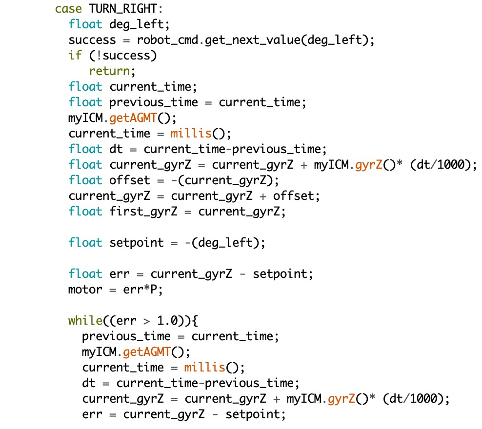
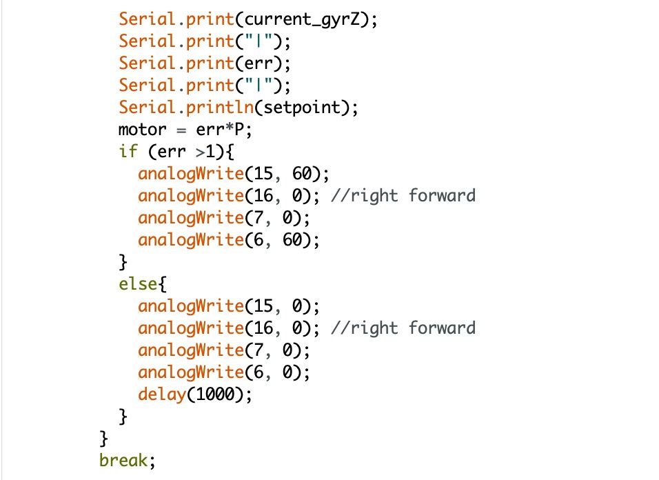
The code below are the screenshots for the robot turning.
I set the clockwise direction as positive, so, I name it as turn right. The logic is very similar as the CASE for "MOVE_FORWARD".
I have to calculate the setpoint based on the current position of the robot.
The turning degree is set relative to the IMU position.
Note, my code above is inspired by Linda Li from 2022.
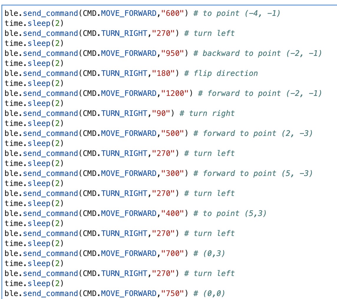
The picture below shows the python code. The distance shown in every "move_forward" is measured in the real map. I run the robot in the lab classroom and get the most appropriate distance to increase the accuracy. As you can see, some degrees are 270, which means the robot is turning left at 90 degrees. It is because I didn't create a separte code for the robot to turn left. In the real life testing, the error caused by the rotational drifting can be ignored. The biggest factor for the inaccurate of the robot moving is the different of the motor speed. My robot always drift to the left even though I increase the speed of the left motor.
Video demonstration and Discussion
The video below shows the robot can pass each point successfully, but it is obvious an open loop control. When I did the code preparation for this lab, my robot works pretty good. And it can move straight and then make a turn accurately. But when I trying to record the video, the code has some issues. The problem is that the robot can not do any movement after I run the command for moving straight. I tried to Serial.print the data, and I realize it is because of the robot will stop moving at a weird point, which does not satisfy the distance I set in the Python code, so the loop will not stop and the move_forward command can not stop. Therefore, the robot can not execute the next command. I tried to ask some of the TAs, and still can not figure out the problems. Due to the time constraint, I just to choose to add an extra command to execuate the open loop control to try to mimic my result.