Lab 5 - Motors and Open Loop Control
Prelab: Diagram
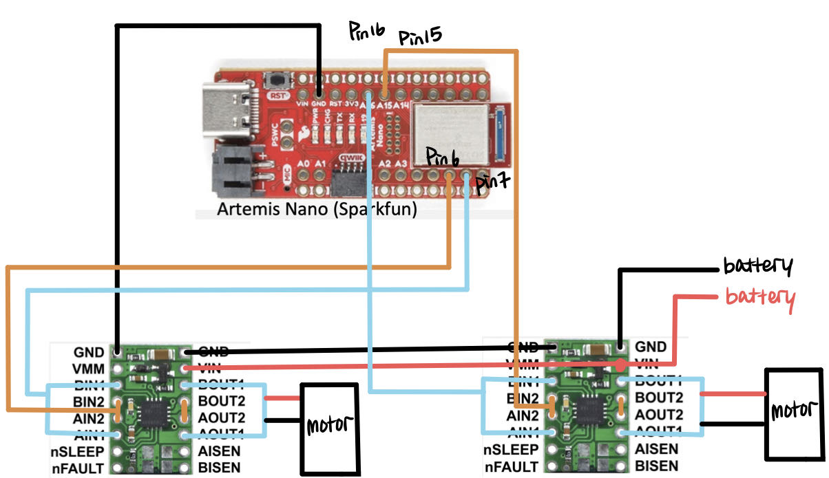
The picture above shows the diagram with your intended connections between the motor drivers, Artemis, and the battery (with a specific pin number). I check the Artemis datasheet and find all the pin with the "~" sign. That means it can have a PWM signal. For the left motor drive, I choose pin 6 and 7. And for the right side motor driver, I choose pin 15 and 16.
Prelab: Battery Discussion
We have two battery choices in total. For the motor, I choose the 850mA to charge it. Compared with the Artemis board, these two motors will cost more energy and use more current to make it works, so it is necessary to have a battery with a larger capacity. Also, using two separate batteries can make sure the Artemis and motors can work independently to make it debug easily.
Task 1: Dual Motor Driver and PWM Testing
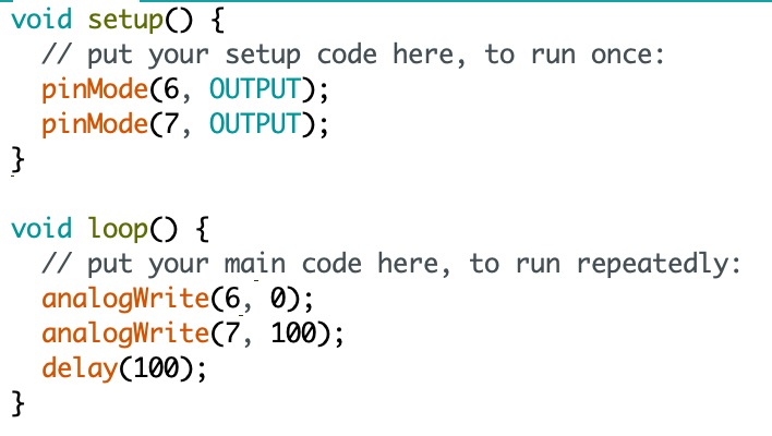
In this task, I test the left side motor as I draw in the diagram shown in the prelab. The code to generate PWM signals is also shown below. I set up the pin number and then use the analogWrite to get the power for the motor driver output. The PWM range is ranging from 0 to 255, so I choose a number almost in the middle to test it. Here, we still need to use the external power supply. I set the voltage as 3.7V, which is the same as the battery provided in this course. The voltage can not be too high, otherwise, the Artemis will be broken.
I use the red and black wire from the power supply to connect the Vin and GND of the motor driver. Two black wires from the oscilloscope should also be connected to the GND. And the two red wires will connect with these two wires from the "out" side of the motor driver. The connection is shown at the very beginning of the video below. And as you can see, on the screen of the oscilloscope, the voltage oscillates in the proper range, which is what we expected.
Task 2: One Wheels Spinning
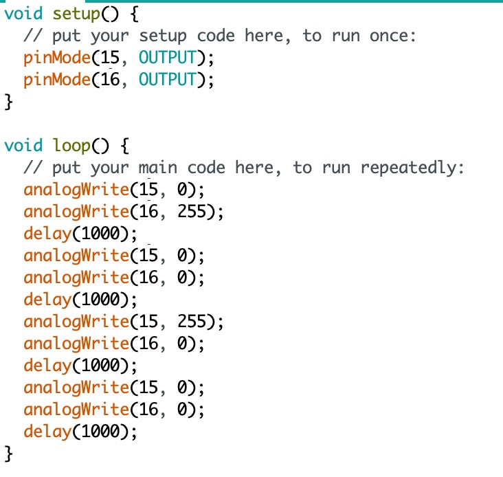
I unscrew the top blue shell from the car, and then cut the LEDs and PCB wires. There are three sets of wires (red as Vin and black as ground) we have to connect, two for the motors and one for the battery. First, I mount one side of the motor and use the external power supply to see if the wheels can move both forward and backward. The code below is what I used to make the wheel move in both directions. The pin I use is 15 and 16. The meaning of my code is that the car moves forward for one second, next, stops for one second, then moves backward, and stops for one second.
The video below shows that one side of the wheel works well and this is charged by an external power supply.
The second video is charged by the battery by soldering the Vin and Ground from both motor driver with the red and black wires from the RC car.
Task 3: Both Wheels Spinning
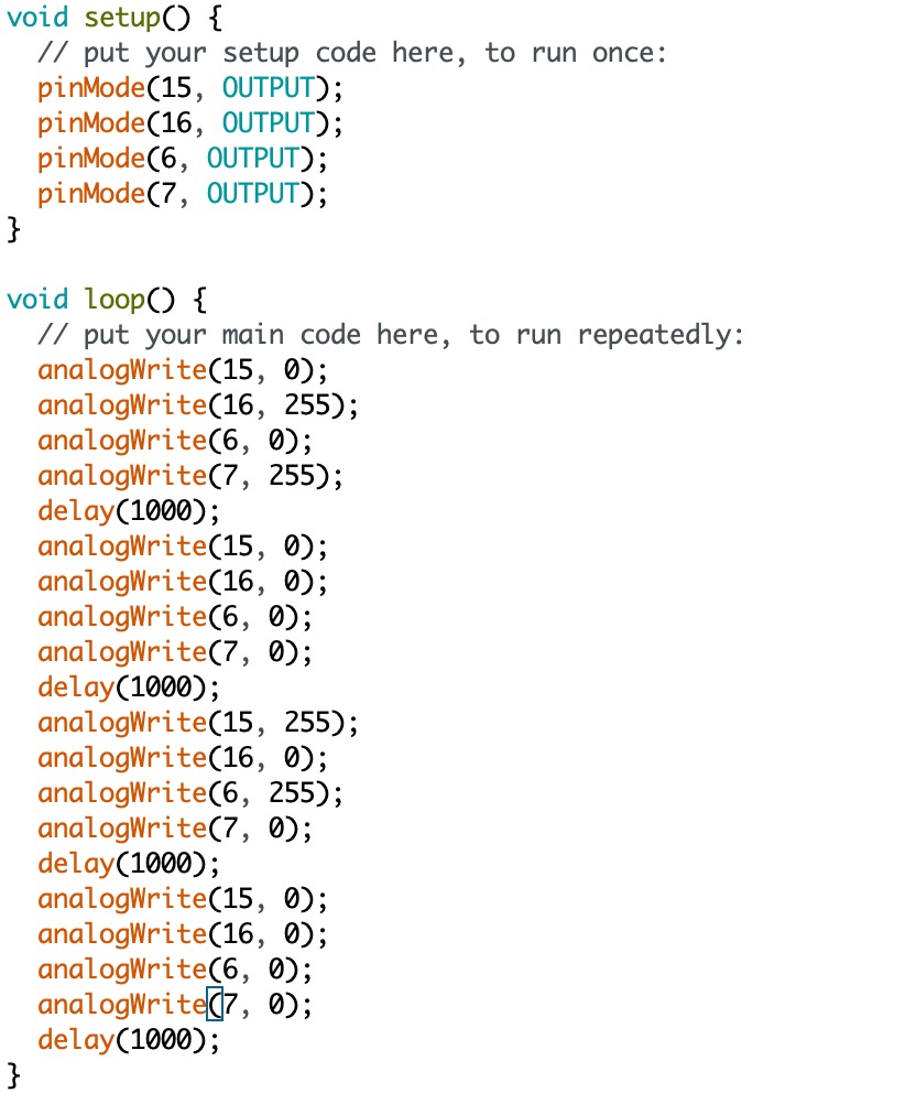
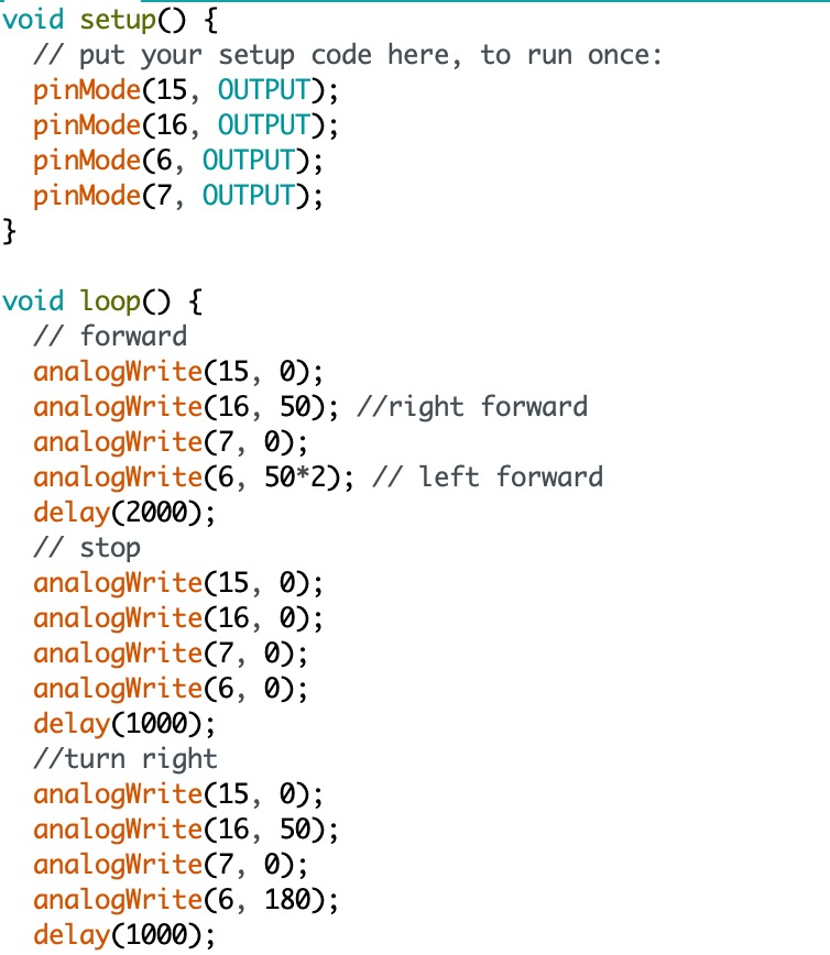
To drive both motors together, we just have to make some small changes based on task 2. It requires defining the pin connected with the other side of the motor, which is pins 6 and 7. In the void loop, the logic is the same as the code from task 2 with the PIN changes. The picture below is the Arduino code I use.
The video below represents the wheel from both sides can work well with the 850mAh battery.
Task 4: Components Secured in the Car
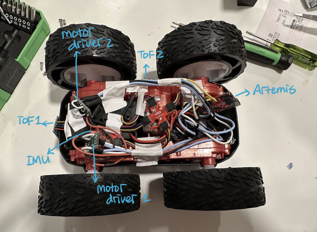
The picture below is all the components secured in the car and I clearly labeled the important components.
Task 5: PWM Value Discussion
To find the lower limit of the PWM, I change the PWM value from the analogWrite. Starting from 10, I gradually add up the value and test it on the floor to see whether it is effective to move. After several test, I found around 45 is the lower limit of the PWM.
Task 6: Calibration Demonstration
I set the PWM value as 50 to do the calibration implementation. When I set the same PWM value to both motors. As you can see in the video shown below, the RC car is drifting to the left.
To calibrate that, I have to increase the PWM value of the left-side motor to increase the voltage applied to the motor, which will increase the wheel speed. After several tries, I found that if the PWM value from the left side can be times 2, the car can almost move in a straight line. In the video below, there is still a little bit of drifting to the left. It is because the starting direction is not strictly straight, so it will cause some inevitable error.
Task 7: Open Loop Code and Video
The video and the code below shows how the car acts when I add an extra set of code to make it turn right.
Additional task for 5000-level Students
Task 1: AnalogWrite Frequency Discussion
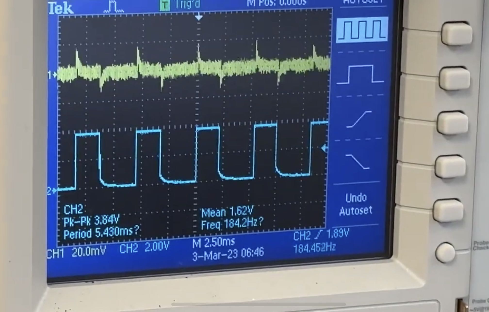
As you can see above, this is the screenshot in the video of the PWM signal in task 1. Each horizontal block represents 2.5ms, so the period of the PWM signal is about 5.5ms. Therefore, the frequency is 1/5.5ms = 182Hz. In labs 3 and 4, we experimentally found the speed to get ToF and IMU data. ToF is 30ms and IMU is about 2-5ms. So the frequency for ToF is smaller than motors, and the frequency for the IMU is almost the same as the motors. So, the frequency for the PWM signal is fast enough to catch and then make some reaction based on the surrounding environments. If we generate a faster PWM signal, the motor can respond more quickly in some extreme situations.
Task 2: Lowest PWM Value Speed Discussion
Due to the static friction being larger than the friction of the car moving, we have to set a larger initial speed to drive the motor to start to move. So I set the starting PWM value as 60. And by doing several experiments, I found the time that robot settles at its slowest speed is 500 ms and the lowest PWM value at which you can keep the robot running once it is in motion is 40. As you can see in the video below, the car moves very slowly. When I try below 40, the motor is not effective in the car moving.