Lab 3-Time of Flight Sensors
Objective
This lab mainly focuses on the performance of sensors connecting to the robot. We have to fully understand how the ToF works and test the sensor's mode, speed, and reliability. In this lab, we will also learn how to do soldering.
Prelab Discussion
By checking the datasheet provided in the lab guideline for the VL53L1X, the device has a maximum speed of 400 kbits/s and the I2C address is 0x52.
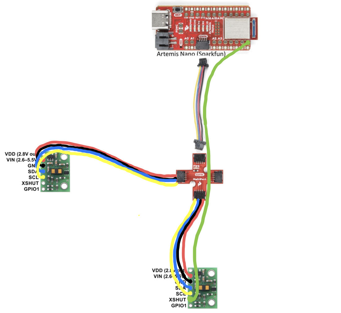
Normally, the ToF is connected with the Artemis individually and the I2C address is not a big problem even if two ToF has the same address number. In some situations, when we want the two ToF to connect with the Artemis board at the same time, only one ToF can work because they have the same I2C address. To solve it, one of the sensor should add an extra wire to connect with the XSHUT on the ToF and pin8 on the Artemis board. In Arduino code, we could first set the XSHUT as LOW to shut down one sensor, and then we have to change the I2C address for the other sensor. After that, we could reset the XSHUT to HIGH. These two ToF then will have a different addresses and they can work well at the same time.For the placement of the sensor, I choose to place these two sensors at 90 degrees. So, it can make sure it can detect obstacles from both front and side. This can largely improve the safety of the robot. But if the obstacles are on the other side or the behind the robot, it will miss.
The picture provided below is the sketch of the wiring diagram.
Task 1: ToF sensor connected
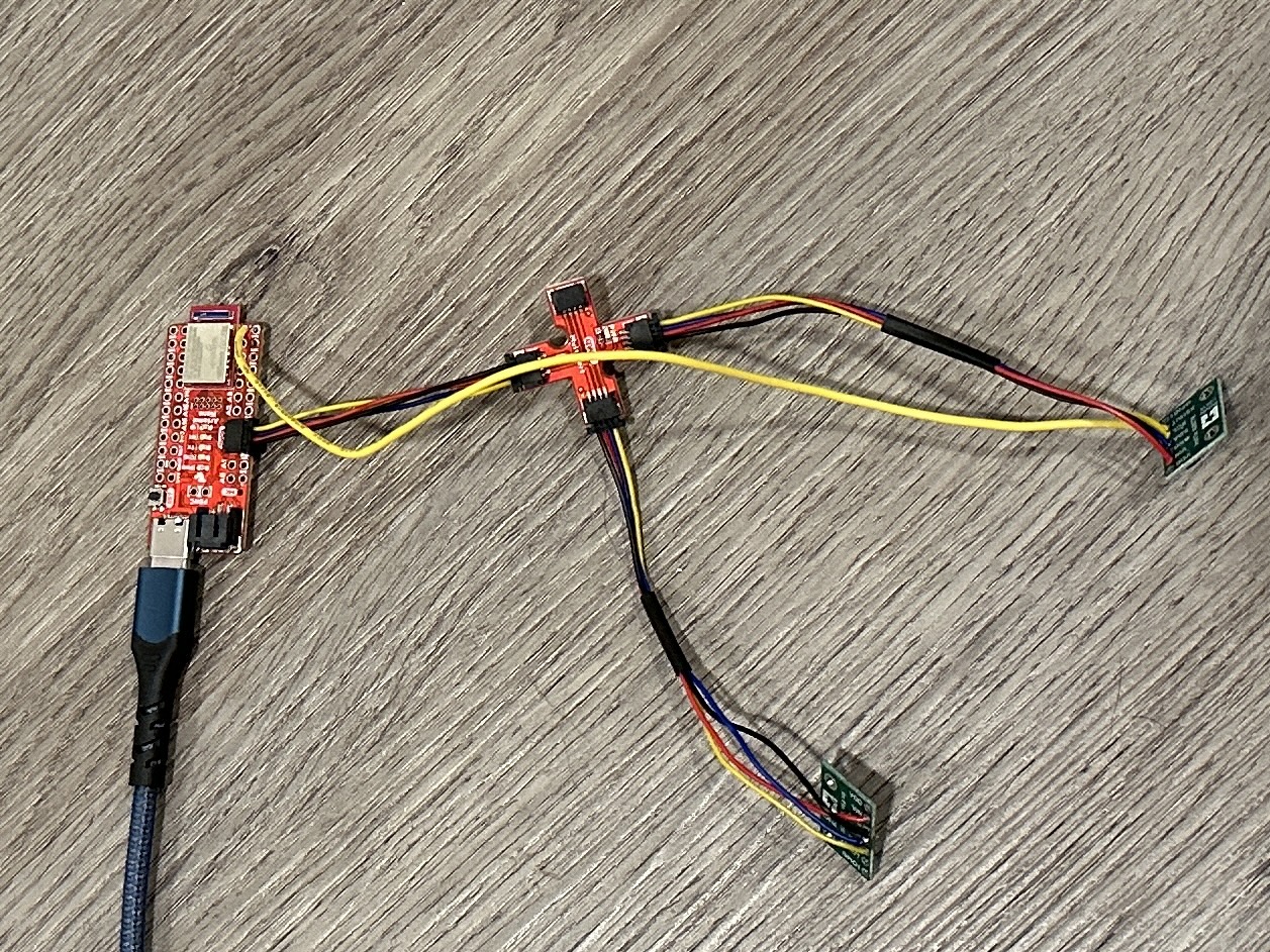
The picture below is the physical connection of my ToF sensor and QWIIC breakout board.
Task 2: Artemis scanning for I2C device
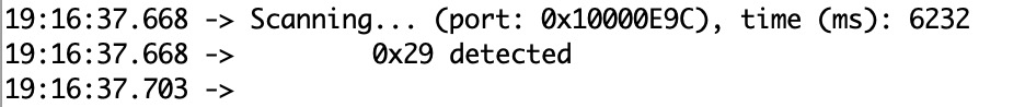
The default I2C address is 0x52, which is 0101001. It can be get from the datasheet of VL53L1X. The scanning for the I2C can be found by running the example code "Example05_Wire_I2C". The address is shown on the serial monitor. The screenshot is shown below, which is 0x29. That is because the LSBit is in R/W format and the address is shifted. Therefore, the address is matched.
Task 3: Sensor Data
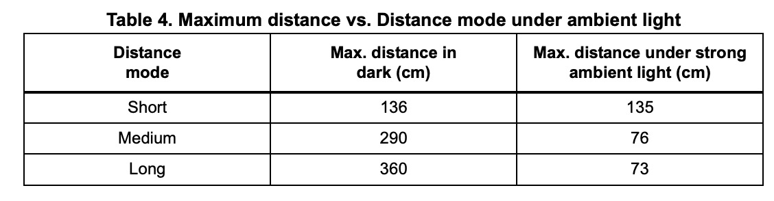
The table above is the Maximum distance vs. Distance mode under the ambient light table from the datasheet. There are three different modes in total: short, medium, and long. We can get some simple relationships from the data provided. With the long-distance mode, it has the biggest impact under strong ambient light. And the short-distance mode has almost no impact under strong ambient light.
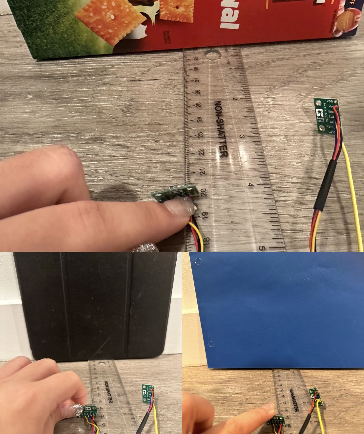
For the robot, it should be better to choose the short-distance mode. The robot is always used in some dangerous, dark, or accuracy-needed situations. So, it is important to exclude the surrounding impact. To get the measured distance, the picture below shows how I setup my experiment.
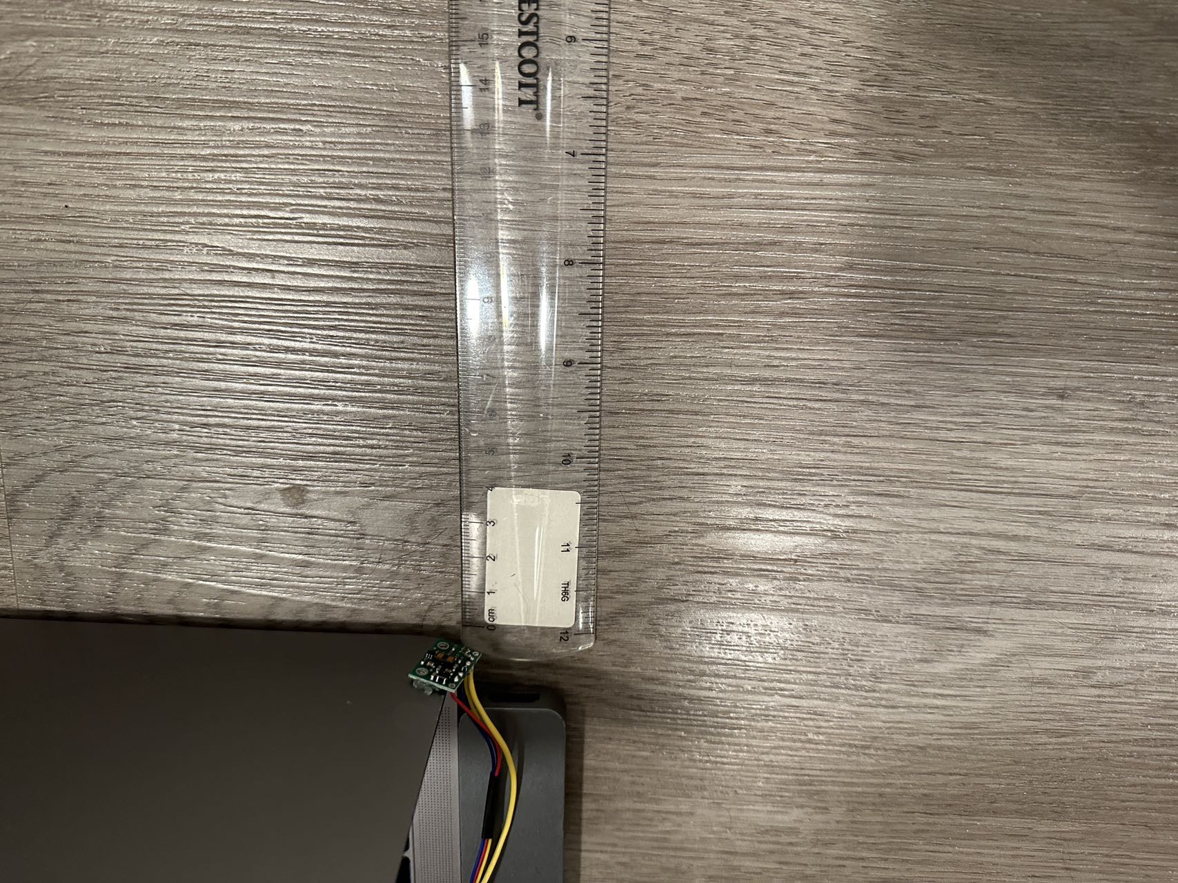
With the short-distance mode, I gathered the data about measured distance and actual distance by using the code found in "Example1_ReadDistance". The plot shown below is made by MATLAB.
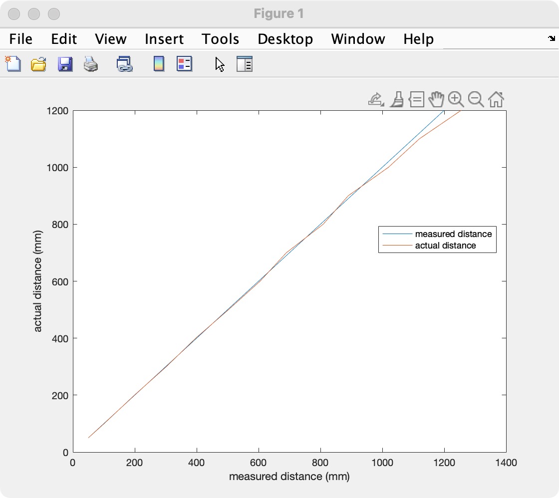 The distance measured is very accurate that two lines on the plot only have a very small gap.
But as the distance gets bigger, it becomes less accurate. The rannging time is around 54ms.
The distance measured is very accurate that two lines on the plot only have a very small gap.
But as the distance gets bigger, it becomes less accurate. The rannging time is around 54ms.
Task 4: 2 ToF Sensor
By using the method mentioned in the prelab discussion, I first use the command "digitalWrite(8, LOW);" to shut down the XSHUT connecting with pin 8 on the Artemis board. Then, "distanceSensor1.setI2CAddress" is helpful to change the I2C address of the other ToF. The last step is to change the voltage of the XSHUT by using the similar idea of "digitalWrite(8, HIGH);". Then, two ToF can run together with different I2C addresses. The video below shows the result of two sensors running parallel.
Task 5: ToF Sensor Speed
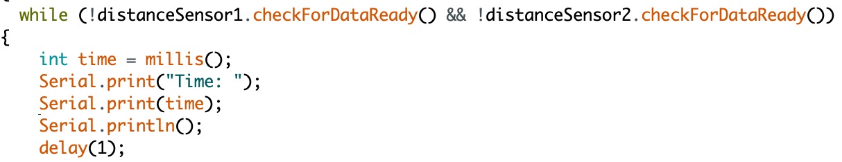
In this task, we still need to modify the code of "ReadDistance". "distanceSensor.checkForDataReady()" command is useful to check if the data is available. So, I set up a while loop to check both sensors. The code is shown above. As you can see shown in the screenshot below, there are 30 ms to get the next distance data. The speed of getting distance is not dependent on the Artemis. ToF is the limitation.
Task 6: Time vs. Distance
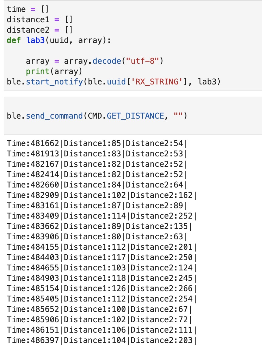
This task is to send these two distance data from the Artemis board to the computer by Bluetooth. I write my Arduino code in "ble_arduino" in lab 2 and generate a case called GET_DISTANCE. The logic is very similar to the lab 2 task. But here, we have to add some setup for the ToF sensor. I copied most of them from the example code "ReadDistance".
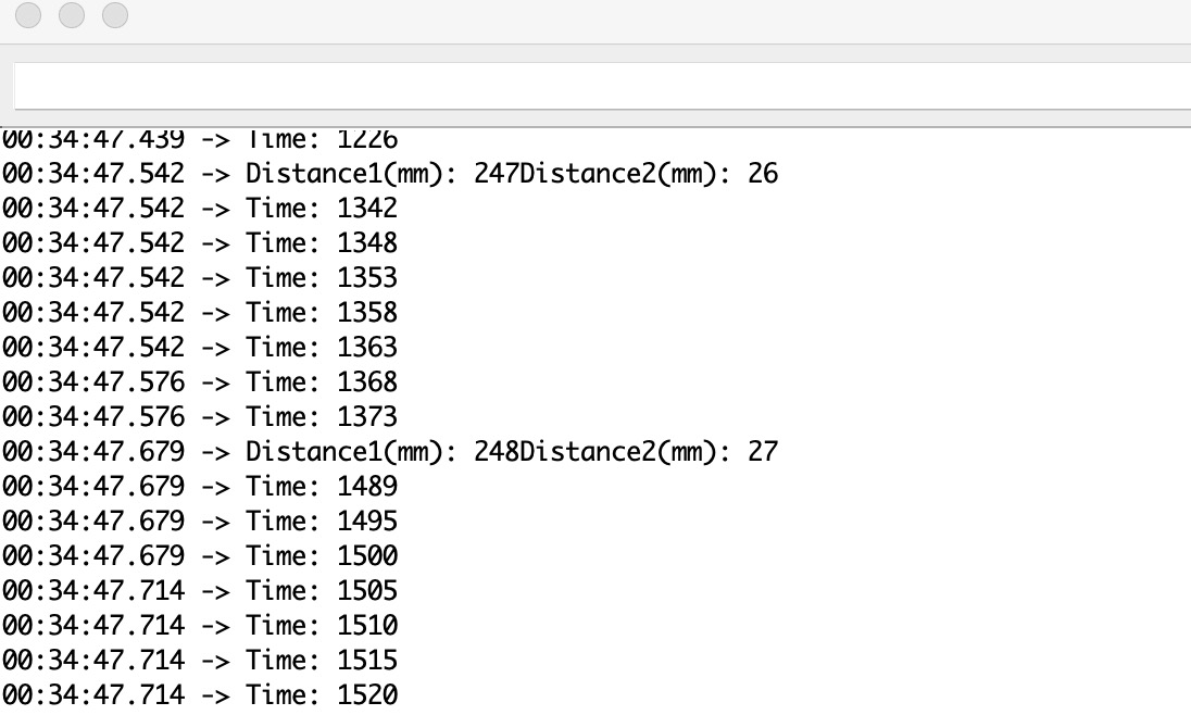
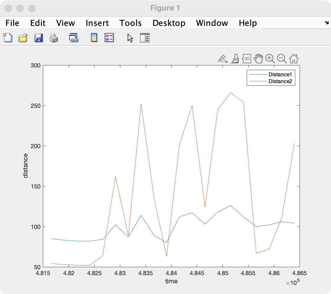
Then I wrote the callback function in Python to print the data received. The screenshot below is the data I got by just randomly shaking the sensors. The Time vs. Distance plot is generated by MATLAB.
Additional tasks for 5000-level students
Additional tasks 1:
There are two types of Infrared sensors (aka IR sensors). An active IR sensor contains both the transmitter and receiver, while the passive IR sensor only contains a detector. Active IR sensors usually use LED or laser diodes as the source, like break beam sensors and reflection. Passive IR sensors usually use the radiates energy from the object as an IR source/transmitter, like Thermocouple-Thermopile and Bolometer.The pros of active IR sensor is that they identify movement in the daytime and evening dependably. The sensor will detect the item without any contract with the item. The disadvantage of a passive IR sensor is that it does not operate greater than 35 degrees C and is insensitive to very slow motion of the objects.
Additional tasks 2:
This task is required to test if there's any influence on the color and texture. The picture I showed below is three different textures and color backgrounds. I put the distance with 10cm, 20cm, and 30cm separately to use the ToF sensor to measure the distance. The results shown in these three backgrounds only have some small differences, like 1-5 mm. This can be neglected because I use my hand to hold the ToF which will cause some small errors. Therefore, based on the experiment I designed, the ToF sensor is not sensitive to the colors and textures.