Lab 4 - IMU
Task 1: Setup The IMU
The picture below shows the picture of my Artemis IMU connections.
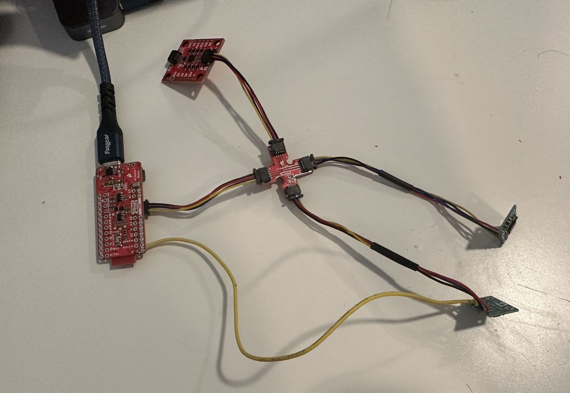
To set it up, we have to first install the SparkFun 9DOF IMU Breakout from the library manager. Then, the example code can be found from example/SparkFun 9DOF IMU Breakout/Arduino/Example1_Basics. The IMU code works perfectly and I attached the screenshot of the Serial Monitor below.
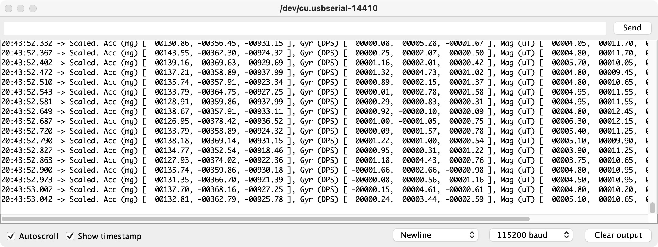
The AD0_VAL has two values, 0 and 1. The definition of the AD0_VAL is the value of the last bit of the I2C address. The default value of the IMU is 1, and when the ADR jumper is connected, the value becomes 0. In this lab, we do not have the ADR jumper, so the AD0_VAL we set should be 1.
After running the example code, I check the Serial Monitor and compare the data shown for the Accelerometer and Gyroscope. I randomly move the IMU board and check the value changed. It shows that when I speed up the board, the Accelerometer value will increase and when I rotate the board, the Gyroscope value will increase.
Task 2: Accelerometer
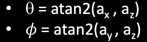
To convert accelerometer data into pitch and roll, I use the equation posted in the lecture, which is shown above. The Arduino code for that are "float pitch_a = atan2(myICM.accX(),myICM.accZ())*180/M_PI;", and "float roll_a = atan2(myICM.accY(),myICM.accZ())*180/M_PI;". To use M_PI, we have to add "#include math.h" at the very beginning. The two pictures shown below are the SerialPlot screenshots for pitch and roll moving from -90 to 0, and then to 90 degrees. The first one is pitch and the second one is roll.

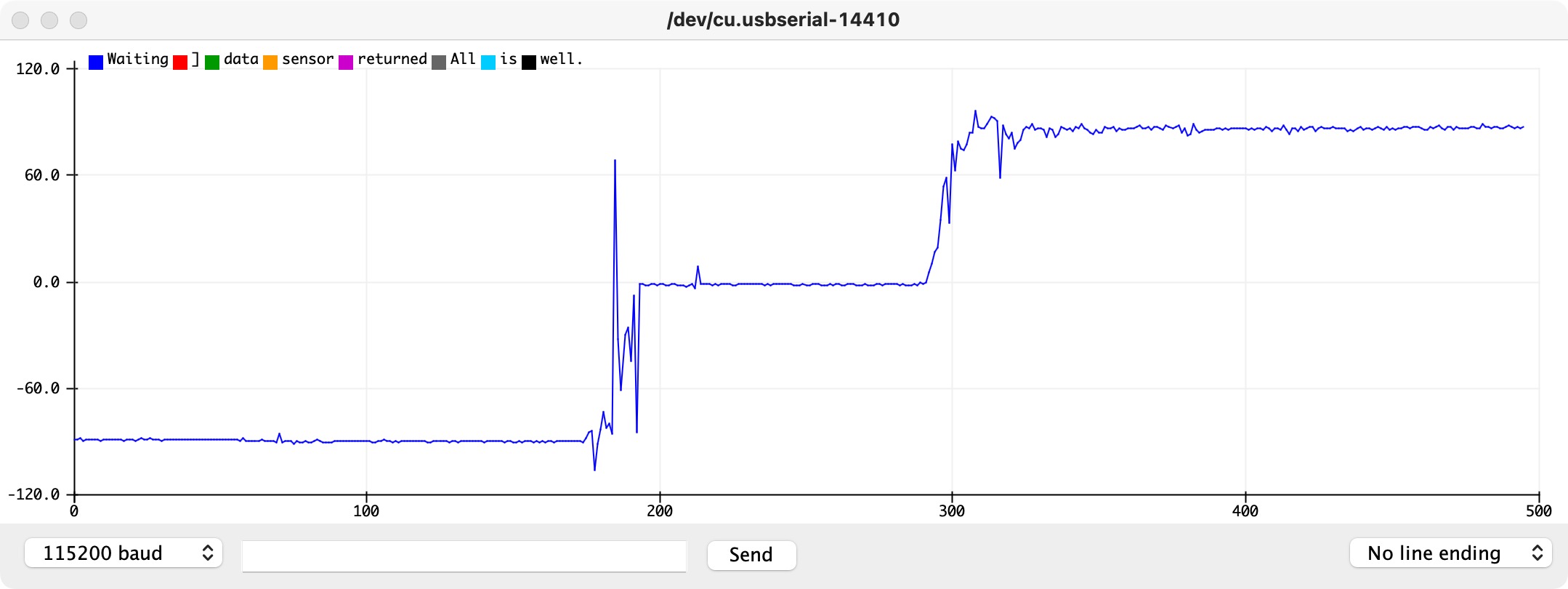
As we can see in the screenshots, even though there's a little noise, the angle we get is pretty accurate. It seems to only have a 1-degree difference between the angle we want, so overall, it performs well.
I use the "Fourier Transform in Python" example as a reference to get the fft for the pitch and roll data separately. In my data set, I set the sample rate as 50, and it gathered in 2 seconds. So, I will have 50*2 = 100 data points in total. Four pictures below are the result of this task and they are all perfectly labeled.
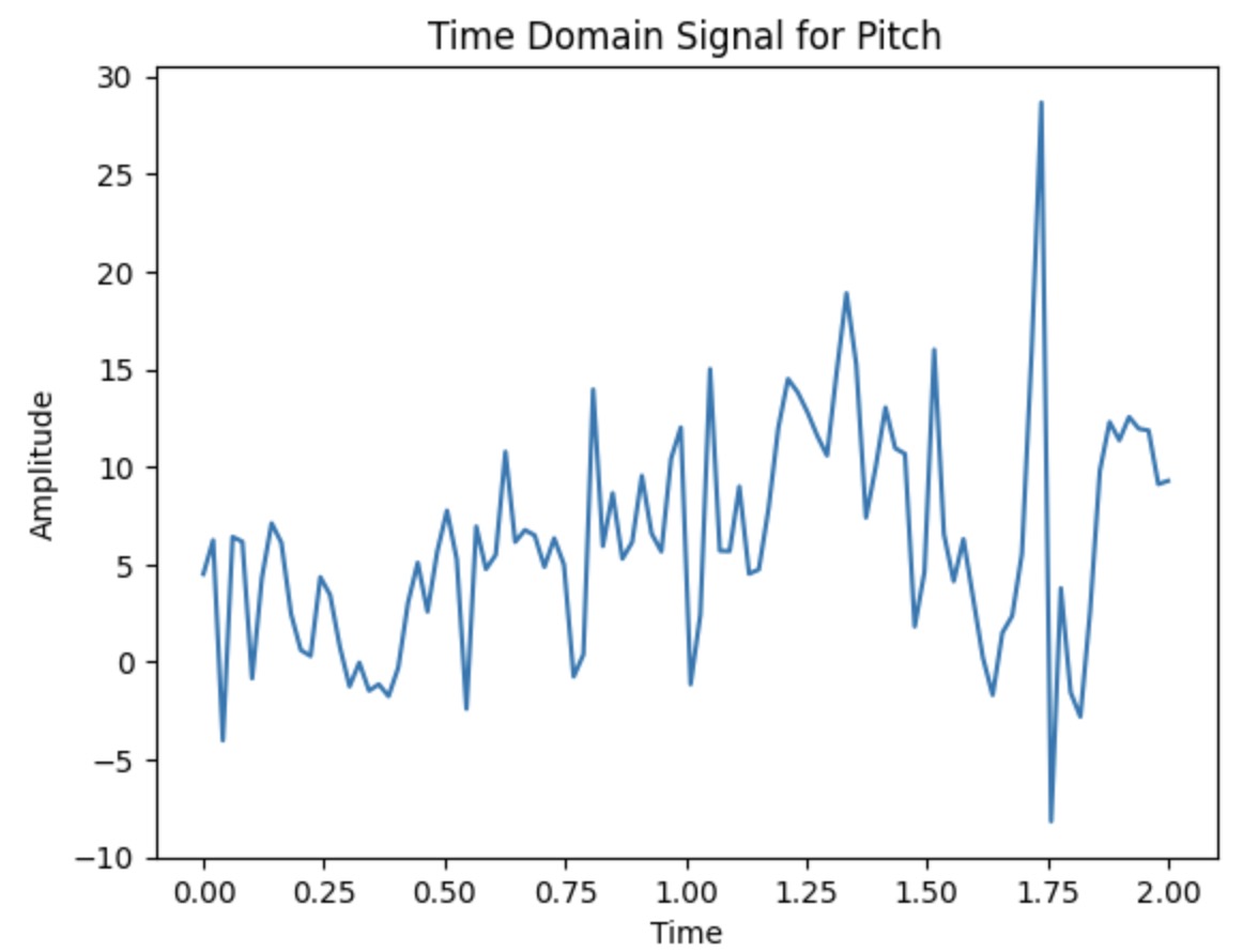
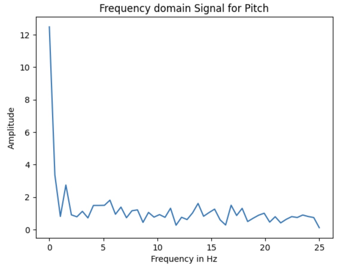
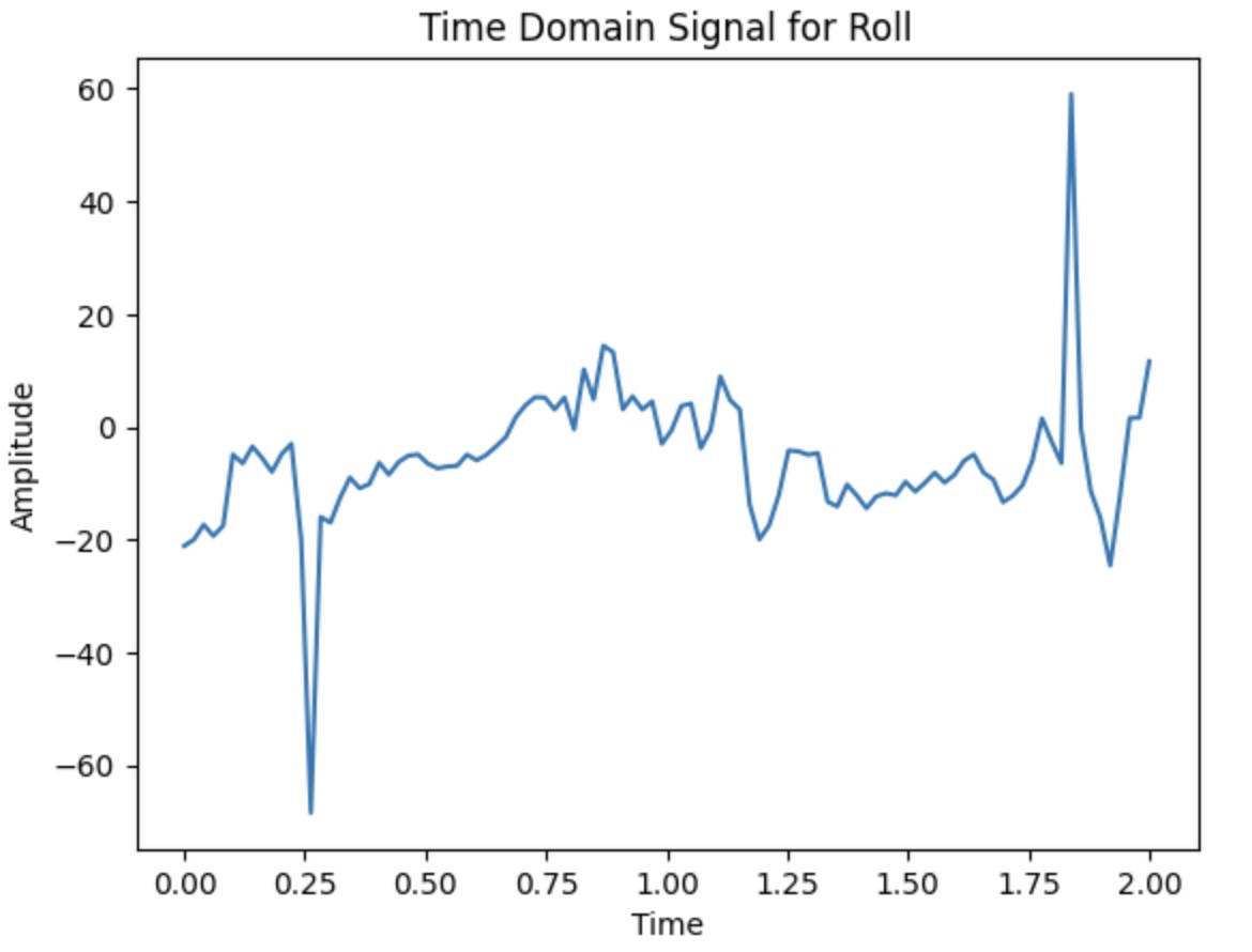
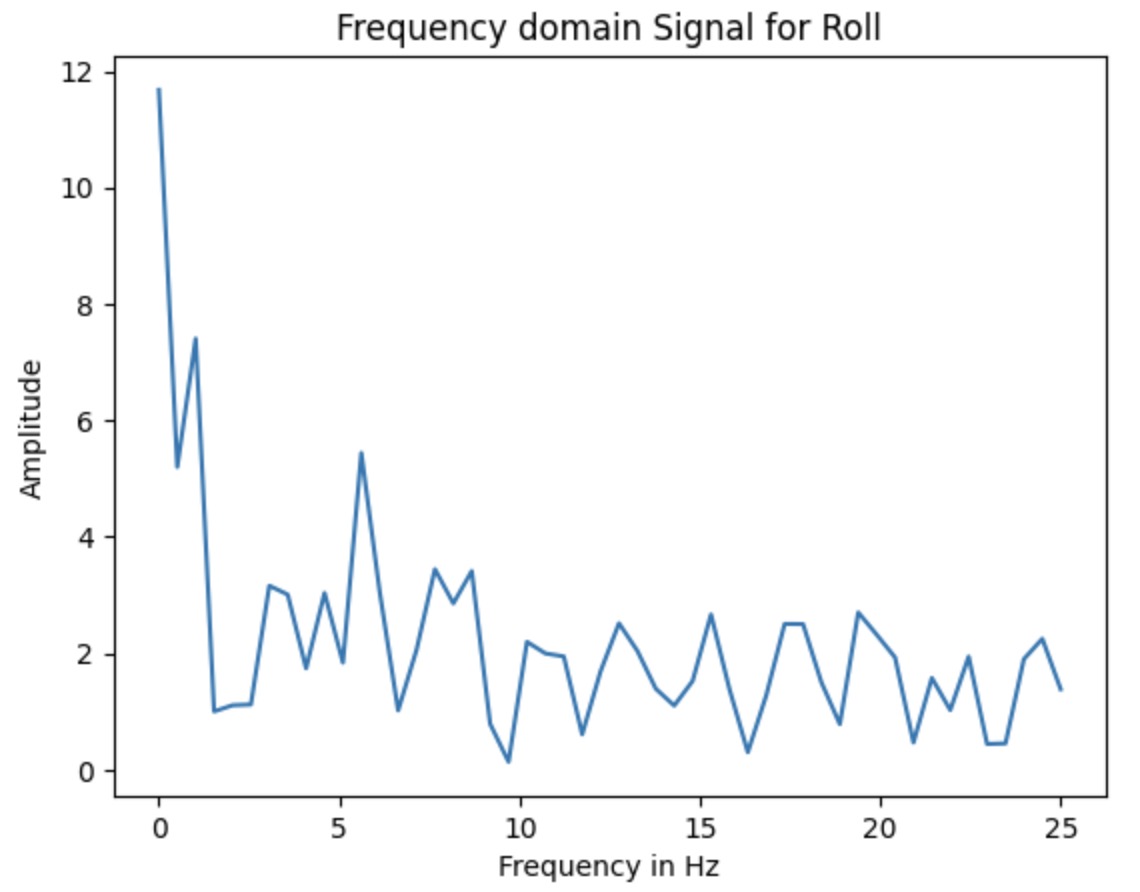
By looking at the result of the Frequency Domain Signal for both pitch and roll, the amplitude is all nearly within the value of 2. I don't think we need to add any low-pass filter for that.
Task 3: Gyroscope

This task requires getting the angle from the Gyroscope value. I use the equation listed in the lecture slides to calculate it, which is shown above. The video below shows the resulting angle change as I rotate my IMU board.
		long time_current;
		time_current=millis();
		float dt;
		dt=(float)(time_current-time_previous)*0.001;
		time_previous=time_current;
		pitch_g = pitch_g - (sensor->gyrX())*dt;
 		roll_g = roll_g + (sensor->gyrY())*dt;
		yaw_g = yaw_g + (sensor->gyrZ())*dt;
I rotate the IMU board in three different ways and each way will correspond to pitch, roll, and yaw. The plot in the video is reasonable.

		complimentary_roll = (complimentary_roll + roll_g*dt)*(1-0.1) + roll_a*0.1;
		complimentary_pitch = (complimentary_pitch + pitch_g*dt)*(1-0.1) + pitch_a*0.1;
Adding a complimentary filter is useful here, as shown in the video, the plot becomes more smooth, which means it reduces the noise. The equation I use is getting from the lecture notes and I set the alpha value to 0.1 to get the best performance. After adding the such filter, our IMU will be not susceptible to drift or quick vibrations.
Task 4: Sample Data
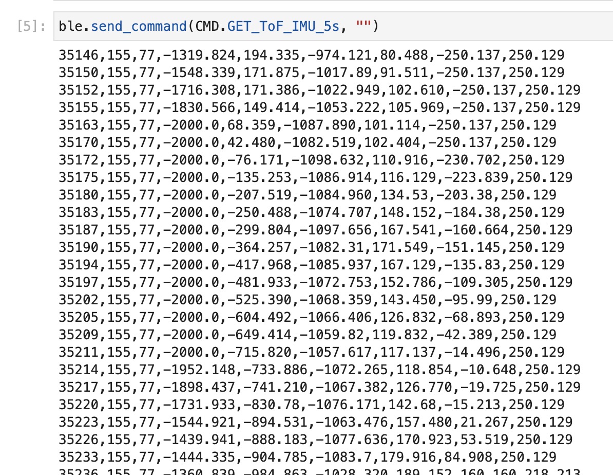
As we can see from the data screenshot, the speed of sampling is about 2-5 milliseconds when gathering one set of data.
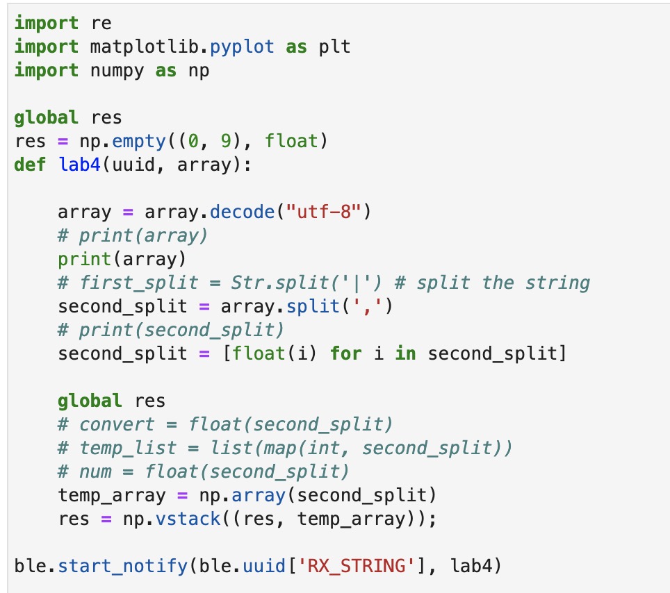
To get the data through Bluetooth, I use a similar idea from lab 2. I create the new case and use "tx_estring_value" to append all the ToF distances and IMU data we need. And then, I use the notification handler to receive the data from the Artemis to the computer. The two pictures below are the python code for the Notification handler and the data we finally get.
There is one trick I should notice, if I store my data at such quick speed, I can not gather the data lasting 5 seconds. The Memory will be full as we discussed in lab 3.
Task 5: Cut the Coord
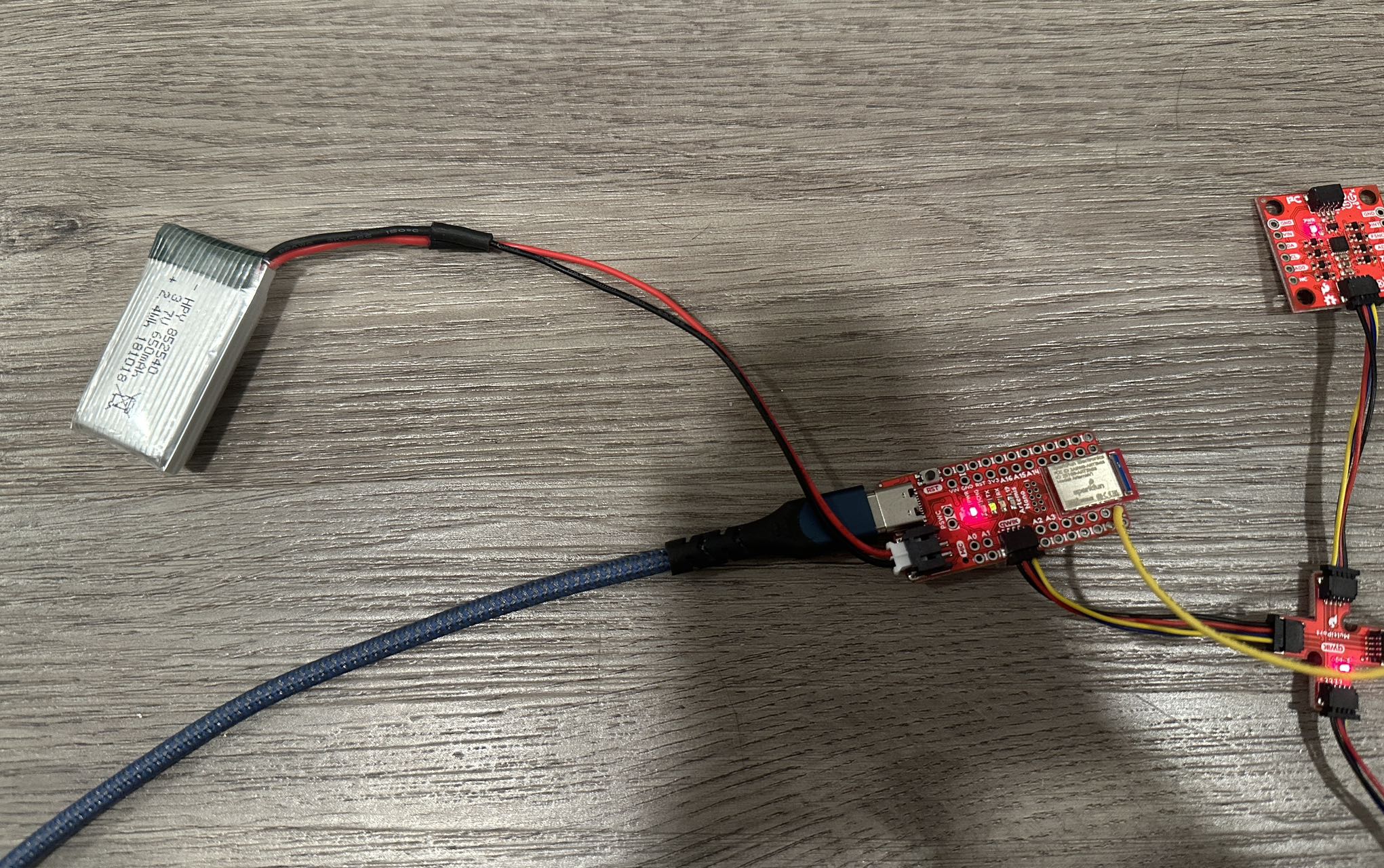
There are two types of batteries we can choose from, 650 mAh and 850 mAh. I would like to choose the 650 mAh to connect with the Artemis because those electronic kinds of stuff will use less battery capacity compared with the motors from the car. So, I could leave the 850 mAh to charge the car. The picture below is my Artemis connected to the 650mAh battery.
Task 6: Record a Stunt
The video below is the Stunt without the Artemis board. I can feel the RC car is very sensitive to the controller. It moves backward and forward very fast.
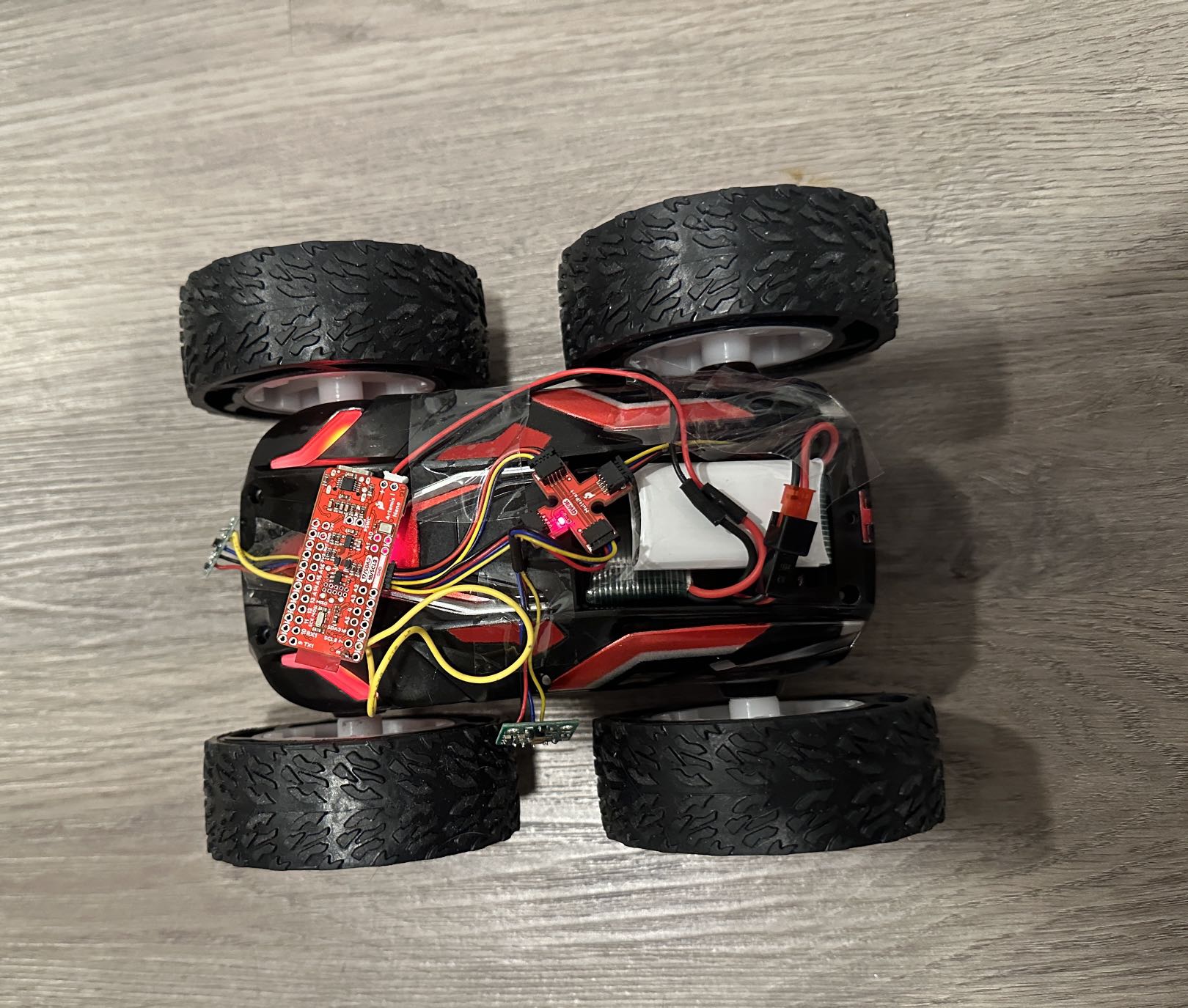
The video below is the Stunt with the Artemis board. And I gather the data from the Artemis board and plot it in Python. I also attached the picture of my RC car with Artemis board on it.