Lab 11 - Localization (real)
Task 1 - Test Localization in Simulation
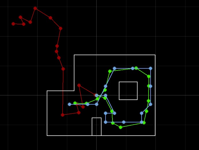
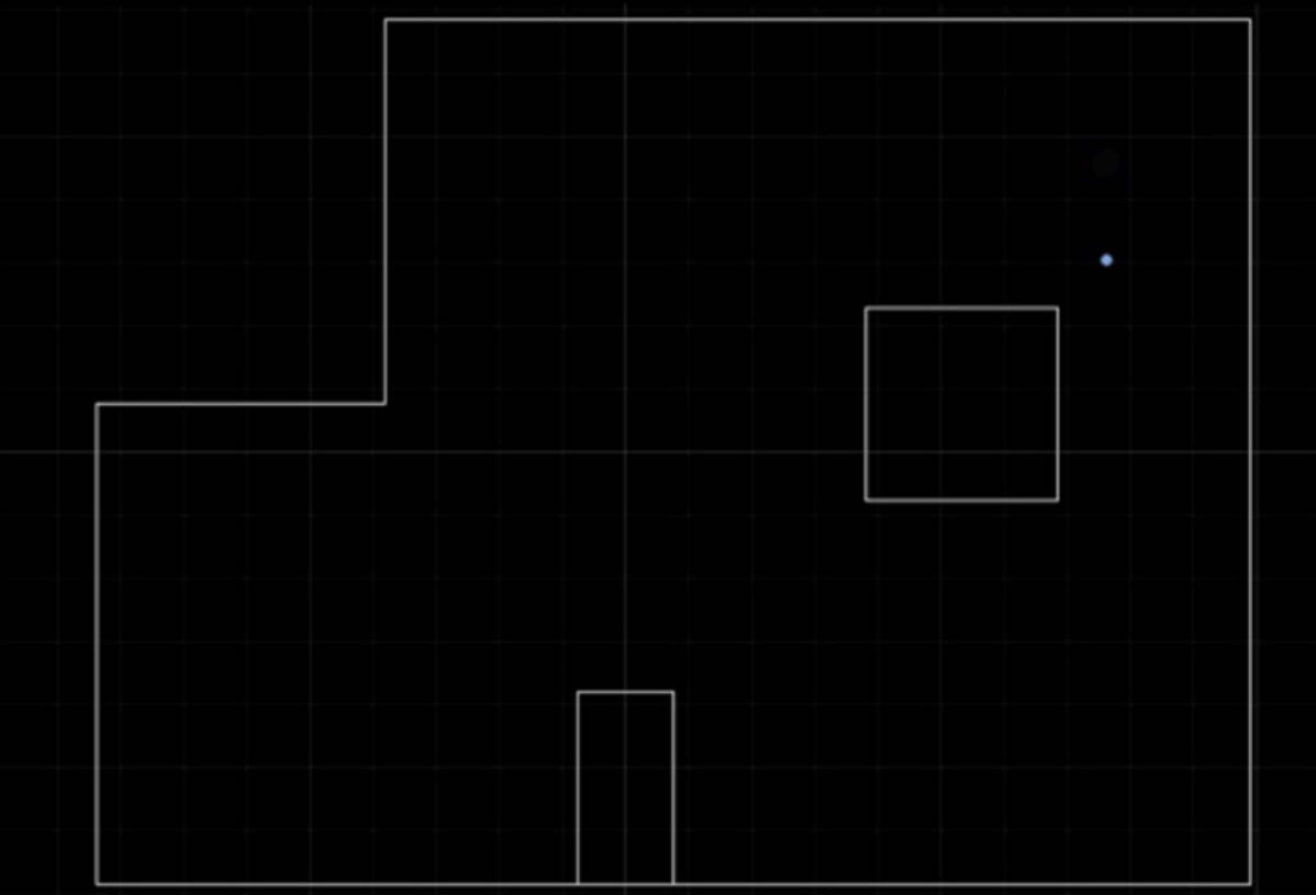
The picture above shows the Localization testing in Simulation with the red line represents odometry reading, green line represents the ground truth, and the blue line represents the belief. The testing is what we expected as the result shown in lab 10.
Task 2 - Implementation
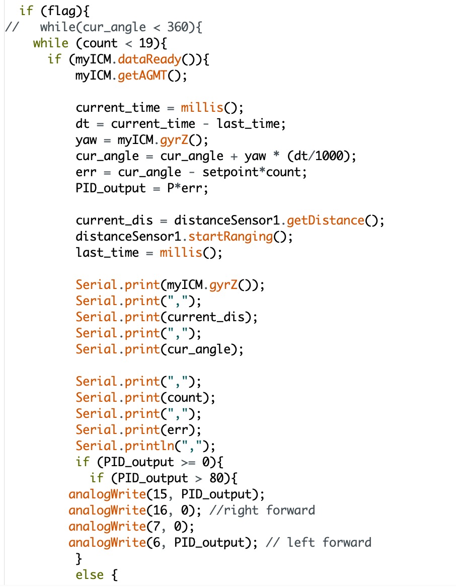
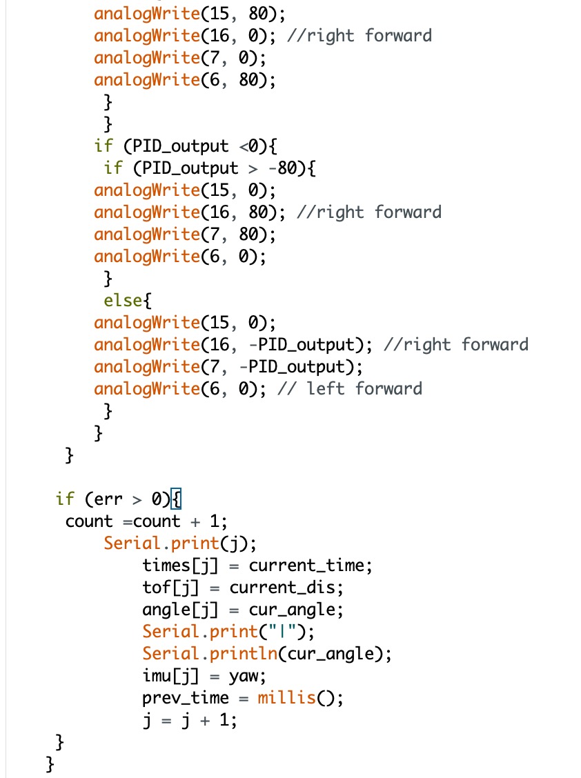
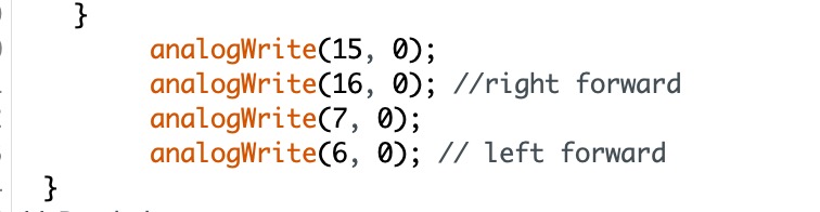
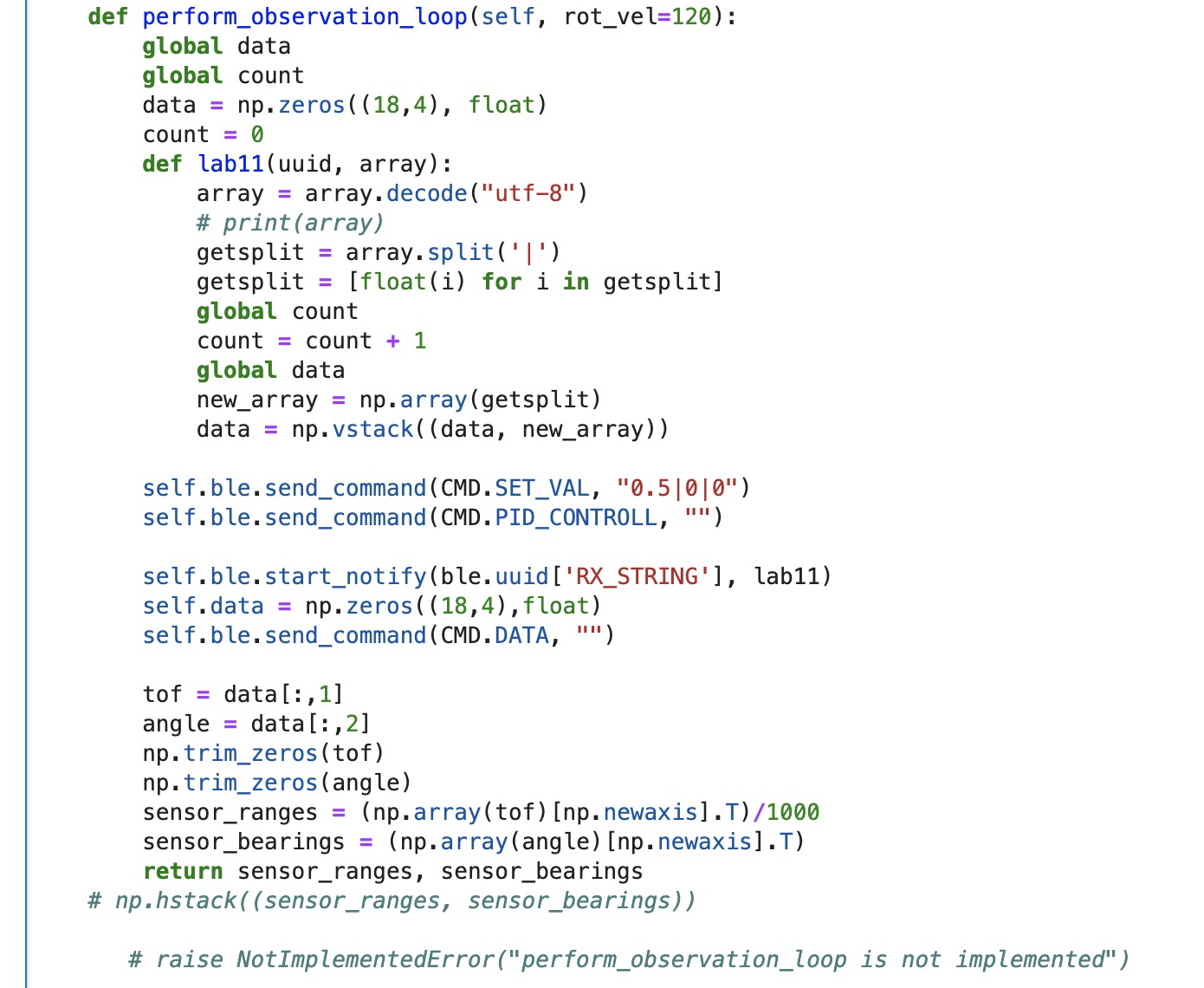
To do the localization in the real map, we are required to get the ToF sensor data every 20 degrees rotation. So, we need to make our robot rotate from 0 degree and stop at the 360 degrees with 20 degree increments. The number of the data set is 18. The picture below shows the Aruduino side of implementation. The code for this lab is modified based on lab 9. In lab 9, I use the rate of change of angle to control the robot, but here, I use the angle to do the P control.
Then, I need to implement my python code. I implement the notification handler and arrange the data receeived into a numpy array. To get the array that we required, I also apply the code "np.array(array)[np.newaxis].T" to convert the list to a numpy column array. Finally, I return the ToF sensor values and the angle values array as we expected.
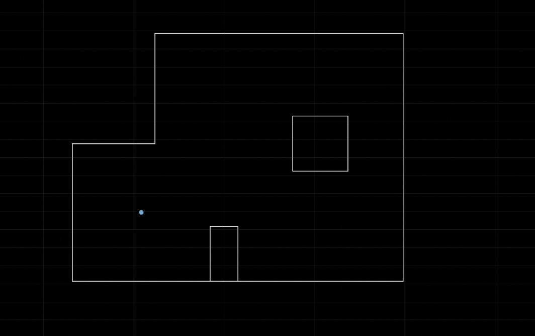
(-3 ft ,-2 ft ,0 deg)
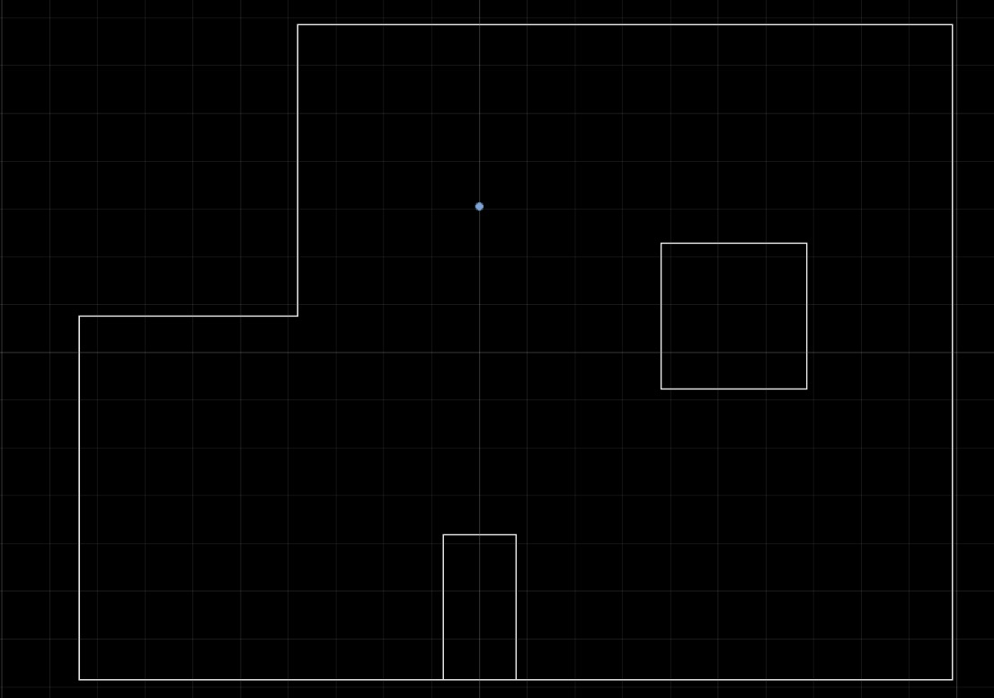
(0 ft,3 ft, 0 deg)
(5 ft,-3 ft, 0 deg)
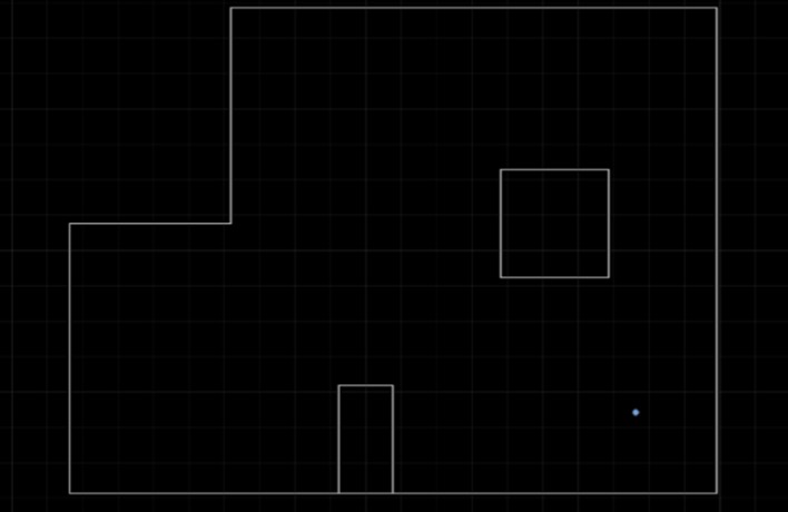
(5 ft,3 ft, 0 deg)
Discussion
Overall, I think the result I got is pretty good. The accuracy rate is 50% in my result. The results for points (-3,-2) and (5,-3) are accurate. But the points (5,3) and (0,3) have one cell error. And both of them have one feet difference along the vertical axis. I think the reasons are the sensor noise and the rotational drifting. Also, there are less obstacle around these points with shorter distance. When the ToF sensor trying to measure the longer distance, the accuracy will decrease. At the mean time, when I run the robot with my code provided above, sometimes it will appear some drifting due to the friction force. That is also a possible factor to cause the inaccuracy of the localization.